Cisco Firepower Threat Defense IKEv2 VPN with Dynamic VTI using Pre-shared Keys
Dynamic VTI
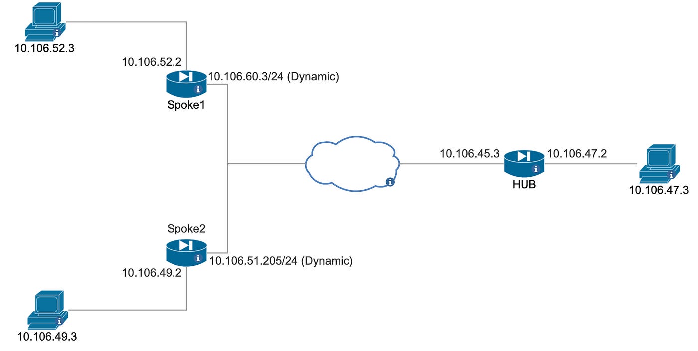
Dynamic VTI provides highly secure and scalable connectivity for site-to-site VPNs. Dynamic VTI eases the configuration of peers for large enterprise hub and spoke deployments. A single dynamic VTI can replace several static VTI configurations on the hub. You can add new spokes to a hub without changing the hub configuration.
In this configuration, the VPN uses dynamic routing protocols to dynamically exchange routing information between the hub and spoke sites, allowing for automatic updates to the routing table when new networks or subnets are added. The dynamic peer IP configuration allows for the spoke sites to have dynamic public IP addresses, which can change over time. This can be useful in cases where the spoke sites are using dynamic IP addresses.
This is useful where you may need to rapidly deploy a varied number of sites and do not want to have to reconfigure the hub router everytime a new site is activated.
Prerequisites
Requirements
Make sure you have configured the Cisco Firepower Threat Defense with IP addresses on the interfaces, and have basic connectivity before you proceed with this configuration example.
Components Used
The information in this document is based on this software version:
- Cisco Firepower Threat Defense FTD Software version 7.3 and later.
- Cisco Firepower Management center FMC Software Version 7.3 and later.
The information in this document was created from the devices in a specific lab environment. All of the devices used in this document started with a cleared (default) configuration. If your network is live, make sure that you understand the potential impact of any command.
Configuration Steps
HUB DVTI Configuration on FTD
Step 1: Define the Loopback Interface for HUB FTD
- Choose Devices > Device Management
- Click the Edit icon next to the device on which you want to create a VTI interface.
- Choose Add Interfaces > Loopback interface
Step 2: Create a Dynamic VTI on HUB appliance
- Choose Devices > Device Management
- Click the Edit icon next to the device on which you want to create a VTI interface.
- Choose Add Interfaces > Virtual Tunnel Interface
- Select the Tunnel Type as Dynamic
Choose Dynamic for a dynamic VTI, enter a Tunnel ID in the range of 1 to 10413 in the Template ID field.
- Under IPSec Tunnel Mode, click the IPv4 or IPv6 radio button to specify the traffic type over the IPsec tunnel.
- Under IP Address:
Borrow IP (IP unnumbered): Choose a physical or loopback interface from the drop-down list, the VTI interface inherits this IP address.
Ensure that you use an IP address different from the tunnel source IP address.
Step 12 Click OK
Step 13 Click Save
Step 3: Create a Route-based Site-to-Site VPN
You should configure a Hub and Spoke topology for DVTI. For a hub and spoke topology, you need to configure virtual tunnel interfaces that manage spokes with dynamic VTIs. Dynamic VTI is supported only for a hub and spoke topology.
For a Hub and Spoke topology, you can configure the hub with a dynamic VTI and the spokes with static VTIs.
- Choose Devices > Site To Site
- Click + Site To Site VPN
- Enter a name for the VPN topology in the Topology Name field
- Select Hub and Spoke as the network topology
- Add Local device with Dynamic VTI interfaces as the HUB node
- Add Extranet in the Spoke node section for the devices which are configured with Dynamic IP range for the WAN IP address.
- Configure Preshared key with the IKE options for the deployment as described in Threat Defense VPN IKE Options.
- Click Save
Note: Pre-shared Key Type in IKEv2 Settings cannot be Automatic. Automatic pre-shared key generation is not supported if one or more endpoint nodes are Extranet. Please configure manual pre-shared key
Step 4: Configure Dynamic Routing for the HUB
- Choose Devices > Device Management
- Click the Edit icon next to the device on which you want to create a Dynamic Routing
- Choose Routing and Click OSPF
- Enable the Process 1 and Click +Add to advertise the network/IP/range to peers.
- Add the interface which is responsible for Multicasting the OSPF Hello packets to its peers.
- Click OK and Click Save
Spoke1 Configuration on FTD
Step 1: Define the Loopback Interface for Spoke
- Choose Devices > Device Management.
- Click the Edit icon next to the device on which you want to create a VTI interface.
- Choose Add Interfaces > Loopback interface
Step 2: Create a Static VTI on Spoke appliance.
- Choose Devices > Device Management
- Click the Edit icon next to the device on which you want to create a VTI interface.
- Choose Add Interfaces > Virtual Tunnel Interface
- Select the Tunnel Type as Static
- Enter the name and description for the interface. By default, the interface is enabled.
- Choose Static For a static VTI, enter a tunnel ID in the range of 0 to 10413 in the Tunnel ID field.
- Choose the tunnel source interface from the Tunnel Source drop-down list.
This interface, a physical or loopback interface, is associated with the VTI interface. Choose the IP address of the interface from the drop-down list. You can select the IP address irrespective of the IPsec tunnel mode. In case of multiple IPv6 addresses, select the address that you want to use as the tunnel endpoint.
- Under IPSec Tunnel Mode, click the IPv4 or IPv6 radio button to specify the traffic type over the IPsec tunnel.
- Under IP Address:
Borrow IP (IP unnumbered): Choose an interface from the drop-down list to borrow its IP address. Ensure that you use an IP address different from the tunnel source IP address. You can also choose a loopback interface if it is configured on the device.
- You can use this option for a static VTI interface.
- Click OK
- Click Save
Step 3: Create a Route-based Site-to-Site VPN
- Select Hub and Spoke as the network topology.
- Configure Preshared key with the IKE options for the deployment as described in Threat Defense VPN IKE Options.
- Specify the IPsec options for the deployment as described in Threat Defense VPN IPsec Options.
- Add HUB device with Dynamic VTI interfaces as the HUB node
- Add local device in the Spoke node section for the devices which are configured with Dynamic IP range for the WAN IP address
- Specify the Advanced options for the deployment as described in Threat Defense for Advanced Site-to-site VPN Deployment Options.
- Click Save.
Step 4: Configure Dynamic Routing from Spoke 1 to HUB
- Choose Devices > Device Management
- Click the Edit icon next to the device on which you want to create a Dynamic Routing
- Choose Routing and Click OSPF
- Enable the Process 1 and Click +Add to advertise the network/IP/range to peer
- Add the interface which is responsible for Multicasting the OSPF Hello packets to its peer.
- Choose Point-to-Point in case you wish to specify the neighbors explicitly.
- Click OK and Click Save
Spoke 2 configuration
Step 1: Define the Loopback Interface
- Choose Devices > Device Management
- Click the Edit icon next to the device on which you want to create a VTI interface.
- Choose Add Interfaces > Loopback interface
Step 2: Create a Static VTI on HUB appliance
- Choose Devices > Device Management
- Click the Edit icon next to the device on which you want to create a VTI interface.
- Choose Add Interfaces > Virtual Tunnel Interface
- Select the Tunnel Type as Static
- Enter the name and description for the interface. By default, the interface is enabled.
- Choose Static For a static VTI, enter a tunnel ID in the range of 0 to 10413 in the Tunnel ID field.
- Choose the tunnel source interface from the Tunnel Source drop-down list.
This interface, a physical or loopback interface, is associated with the VTI interface. Choose the IP address of the interface from the drop-down list. You can select the IP address irrespective of the IPsec tunnel mode. In case of multiple IPv6 addresses, select the address that you want to use as the tunnel endpoint.
- Under IPSec Tunnel Mode, click the IPv4 or IPv6 radio button to specify the traffic type over the IPsec tunnel.
- Under IP Address:
Borrow IP (IP unnumbered): Choose an interface from the drop-down list to borrow its IP address. Ensure that you use an IP address different from the tunnel source IP address. You can also choose a loopback interface if it is configured on the device.
- You can use this option for a static VTI interface.
- Click OK.
- Click Save.
Step 3: Create a Route-based Site-to-Site VPN
- Select Hub and Spoke as the network topology.
- Configure Preshared key with the IKE options for the deployment as described in Threat Defense VPN IKE Options.
- Specify the IPsec options for the deployment as described in Threat Defense VPN IPsec Options.
- Add HUB device with Dynamic VTI interfaces as the HUB node
- Add local device in the Spoke node section for the devices which are configured with Dynamic IP range for the WAN IP address
Step 4: Configure Dynamic Routing for the HUB
- Choose Devices > Device Management
- Click the Edit icon next to the device on which you want to create a Dynamic Routing
- Choose Routing and Click OSPF.
- Enable the Process 1 and Click +Add to advertise the network/IP/range to peer
- Add the interface which is responsible for Multicasting the OSPF Hello packets to its peer.
- Choose Point-to-Point in case you wish to specify the neighbors explicitly.
- Click OK and Click Save
Verification of DVTI between HUB and Spokes
Verification on HUB
- Verify if the Phase1 is UP-ACTIVE
- Login to SSH of the FTD
- Enter into “LINA mode” using the below command
# system support diagnostic-cli
# enable
# show crypto ikev2 sa
Note: The HUB can only be a responder, the traffic has to be initiated from the dynamic peer. The Ikev2 negotiation will be initiated by the dynamic peer.
- Verify if the Phase 2 is established with Spoke1 and Spoke2
# show crypto ipsec sa
You could also filter the security association of a specific peer using the below command.
# show crypto ipsec sa peer <ip4/ipv6>
- Verify if the OSPF neighbor is UP with virtual-access interface
- Check the routes learned through OSPF in the routing table
# show route ospf
- Check the OSPF neighbourship formed on the HUB appliance towards the dynamic spokes
# show ospf neighbor
- Check the reachability from HUB to Spoke 1 and Spoke 2
- HUB Firepower
- User LAN personal computer behind HUB Firepower
Verification on Spokes
- Verify if the Phase1 is UP-ACTIVE
Login to SSH of the FTD
Enter into “LINA mode” using the below command
# system support diagnostic-cli
# enable
# show crypto ikev2 sa
- Verify if the Phase 2 is established
# show crypto ipsec sa
You could also filter the security association of a specific peer using the below command.
# show crypto ipsec sa peer <ip4/ipv6>
- Check the OSPF neighbourship formed on the HUB appliance towards the dynamic spokes
# show ospf neighbor
- Check the reachability between Spoke1 and Spoke2 via OSPF
1. Ping from Spoke 1 to Spoke 2
- Check the OSPF routes learnt from the HUB.
Verification with Firepower Management center
- Go to Overview → Site to Site VPN
- To view Detailed information click 👁️ symbol.
- Choose CLI Details to view Phase2 status and VPN session status without accessing the CLI of the FTD
Note: The tunnel status of the Dynamically managed peer will shown as unknown, for more information please refer to the limitations of DVTI on FTD 7.3
Troubleshooting
Clear Security Associations
When you troubleshoot, be sure to clear existing SAs after you make a change. In the privileged mode of the PIX, use these commands:
- clear crypto ipsec sa → Deletes the active IPsec SAs.
- clear crypto ikev2 sa <Peer_IPaddress> →Deletes the active IKE SAs.
Debugging Ikev2
When you Debug Ikev2, ensure to set the conditional debugs to avoid high resource utilization and unnecessary debug messages flooding into the console/CLI
- Debug crypto condition peer <Peer_IPaddress>
- Debug crypto ikev2 platform 127
- Debug crypto ikev2 protocol 127
- Debug crypto ipsec 127
After the Debugs are collected ensure you turn off the debug using below command
- Undebug all
Note: Please Avoid performing debugs without TAC / Consultant’s advisory. It is a risk to perform debugs on a production server.
Limitations of DVTI on FTD 7.3
- VTIs aren’t supported with clustering.
- Dynamic VTI does not support:
- ECMP and VRF
- Clustering
- IKEv1
- QoS
- If a spoke has a dynamic IP address and a hub has a dynamic VTI behind a NAT, the tunnel status will be unknown.
- For a dynamic extranet, when multiple spokes establish a connection, the site-to-site monitoring dashboard does not show the individual tunnels.
